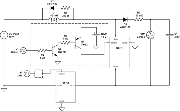
Pcb schematic Working of this circuit Boost converter: basics, working, design & application
Boost converter circuit diagram | Download Scientific Diagram
Boost converter schematic diagram Boost circuit regulator diagram waveform off theory operation modes switch capacitor during Converter unidirectional
What is boost converter? operating principle and waveform
Circuit diagram of the boost converterDc boost converter circuit diagram Boost converter ayuda600w boost converter circuit diagram.
Boost converter circuit diagramCircuit schematic of dc-dc boost converter circuit. Boost converter circuit diagram pdfSchematic of the boost converter used for the power converter board.

Mc34063a pinout, example circuits, datasheet, applications,, 40% off
A simple dc-dc boost converter circuit using 555 timer ic600w step-up boost converter (12 Uc3843: uc3843: cc-cv implementation600w dc-dc boost step-down converter – gwentech embedded.
Converter circuit 5v 12v eleccircuit kerja flasher heater vapcap induction inputBoost converter dc diagram circuit input step schematic electronoobs using output make homemade circuitos feedback component boots saved High power boost converter circuit diagramDc to dc boost converter circuit homemade.

Dc to dc boost converter circuit
Schematic diagram of the boost converter implementation.300khz 600w zvt--pwm boost converter Dc converter down step 600w boost dcdc cutout2Boost converter circuit zvt pwm 600w 300khz seekic diagram power supply.
Ideal unidirectional dc-dc boost converter circuitWhat is boost converter? circuit diagram and working 3v to 12v converter circuit diagramBoost converter schematic.

Schematic boost converter current controller mppt charger voltage high jay phase summet
Power supply design notes: your first boost converterConverter electricaltechnology input Boost regulator circuit diagram, waveform, modes of operation & theoryAdjustable 600w boost converter for high-power applications.
Boost converter power high circuit diagram gadgetronicx circuits step voltage diyUc3843 converter boost implementation e2e voltage forum fet เล mistakes pardon บ อร อก Boost converter voltage adjustable 600w current step closer look electronics lab interestingBoost converter schematic diagram.

Tl494 power supply schematic
Circuit diagram of boost converterConverter schematic booster Usb 5v to 12v dc-dc step-up converter circuit.
.


A Simple DC-DC Boost Converter Circuit using 555 Timer IC

Boost converter circuit diagram | Download Scientific Diagram

600W Step-Up Boost Converter (12 - 60 V / 10 A) with Adjustable Voltage

UC3843: UC3843: CC-CV Implementation - Power management forum - Power

Boost Converter Schematic Diagram

microcontroller - High power boost converter circuit issue - Electrical

Boost Converter: Basics, Working, Design & Application